| Back Take Quiz Next Prev | ||||||
IFR En RouteFrom the AIM "En Route Low Altitude Charts - Provide aeronautical information for en route instrument navigation (IFR) in the low altitude stratum. Information includes the portrayal of airways, limits of controlled airspace, position identification and frequencies of radio aids, selected airports, minimum en route and minimum obstruction clearance altitudes, airway distances, reporting points, restricted areas, and related data." Low Altitude En Route Charts are used for IFR navigation at altitudes below 18,000 feet. Federal Airways The VOR and L/MF (nondirectional radio beacons) Airway System consists of airways designated from 1,200 feet above the surface (or in some instances higher) up to but not including 18,000 feet MSL. These airways are commonly called "Victor Airways" and are depicted on IFR Enroute Low Altitude Charts. The jet route system consists of jet routes established from 18,000 feet MSL to FL 450 inclusive. These routes are depicted on High Altitude Charts. Published RNAV routes, including Q-Routes and T-Routes, can be flight planned for use by aircraft with RNAV capability, subject to any limitations or requirements noted on en route charts, in applicable Advisory Circulars, or by NOTAM. RNAV routes are depicted in blue on aeronautical charts and are identified by the letter “Q” or “T” followed by the airway number. IFR En Route Altitudes Minimum Sector Altitude (MSA) is the lowest altitude which will provide a minimum clearance of 1000 feet above all obstructions located in the area contained within a sector of a circle centered on a radio navigation aid. Minimum En-route Altitude (MEA) is the altitude for an en route segment that provides adequate reception of relevant navigation facilities and ATC communications while complying with the airspace structure and provides the required obstacle clearance. The MEA will assure: • proper reception of navigation aids • two-way communication with ATC • safe clearance or margin from obstacles • adherence to ATC or local procedures Minimum Obstacle Clearance Altitude (MOCA) is the minimum altitude for a defined segment that provides the required obstacle clearance. It is related to a specific MEA. The MOCA is determined and published for each segment of the route. Charts will provide the proper horizontal and vertical separation at those areas where the existence of obstacles could be a factor for the safety of flights. The MOCA will specify minimum vertical separation of 1000 feet from the ground or landmarks. The MOCA may put an aircraft below ATC radar coverage (MVA) and/or below the minimum reception altitude (MRA). The MOCA assures VOR reception within a 22 NM range. The Minimum Crossing Altitude (MCA) is the lowest altitude at which a navigational fix may be crossed when entering or continuing along an airway that will allow an aircraft to clear all obstacles while carrying out a normal climb to the required minimum en route IFR altitude (MEA) of the airway in question beyond the fix. The pilot should climb to the MCA before reaching the intersection; in that way the MCA will not be violated. The Minimum Reception Altitude (MRA) is the lowest altitude on an airway segment where an aircraft can be assured of receiving signals from ground-based navigational aids. Typically, the greater the distance between navigation aids, the higher the MRA. The Minimum Vectoring Altitude (MVA) is the lowest altitude to which a radar controller may issue aircraft altitude clearances during vectoring/direct routing except if otherwise authorized for radar approaches, departures and missed approaches. The Minimum Holding Altitude (MHA) is the lowest altitude prescribed for a holding pattern that assures navigational signal coverage, communications, and meets obstacle clearance requirements. Pilots should be aware of the MHA when entering or starting a holding procedure at all times in order to meet the safety requirements. § 91.177 Minimum Altitudes for IFR Operations. (a)Operation of aircraft at minimum altitudes. Except when necessary for takeoff or landing, or unless otherwise authorized by the FAA, no person may operate an aircraft under IFR below - (1) The applicable minimum altitudes prescribed in parts 95 and 97 of this chapter. However, if both a MEA and a MOCA are prescribed for a particular route or route segment, a person may operate an aircraft below the MEA down to, but not below, the MOCA, provided the applicable navigation signals are available. For aircraft using VOR for navigation, this applies only when the aircraft is within 22 nautical miles of that VOR (based on the reasonable estimate by the pilot operating the aircraft of that distance); or (2) If no applicable minimum altitude is prescribed in parts 95 and 97 of this chapter, then - (i) In the case of operations over an area designated as a mountainous area in part 95 of this chapter, an altitude of 2,000 feet above the highest obstacle within a horizontal distance of 4 nautical miles from the course to be flown; or (ii) In any other case, an altitude of 1,000 feet above the highest obstacle within a horizontal distance of 4 nautical miles from the course to be flown. (b)Climb. Climb to a higher minimum IFR altitude shall begin immediately after passing the point beyond which that minimum altitude applies, except that when ground obstructions intervene, the point beyond which that higher minimum altitude applies shall be crossed at or above the applicable MCA. Changeover Points (COP) The COP is a point along the route or airway segment between two adjacent VORs where changeover in navigation guidance should occur. At this point, the pilot should change the navigation receiver frequency from the station behind the aircraft to the station ahead. The COP is normally located midway between the navigation facilities for straight route segments, or at the intersection of radials or courses forming a dogleg in the case of dogleg route segments. When the COP is NOT located at the midway point, aeronautical charts will depict the COP location and give the mileage to the radio aids. The COP symbol is a squared zig-zag with numbers indicating mileage on the top and bottom. COPs are established for the purpose of preventing loss of navigation guidance, to prevent frequency interference from other facilities, and to prevent use of different facilities by different aircraft in the same airspace. Pilots are urged to observe COPs to the fullest extent. Test questions will ask where the COP exists on a given airway segment. If there is a squared zig-zag, that indicates the COP and mileage. If no squared zig-zag exists on the segment, use the halfway point as the COP. VFR on Top Pilots on IFR flight plans operating in VFR weather conditions may request VFR-on-top in lieu of an assigned altitude. This permits them to select an altitude or flight level of their choice (subject to any ATC restrictions). Pilots desiring to climb through a cloud, haze, smoke, or other meteorological formation and then either cancel their IFR flight plan or operate VFR-on-top may request a climb to VFR-on-top. The ATC authorization contains a top report (or a statement that no top report is available) and a request to report upon reaching VFR-on-top. Additionally, the ATC authorization may contain a clearance limit, routing, and an alternative clearance if VFR-on-top is not reached by a specified altitude. A pilot on an IFR flight plan, operating in VFR conditions, may request to climb/descend in VFR conditions. When operating in VFR conditions with an ATC authorization to “maintain VFR-on-top/maintain VFR conditions,” pilots on IFR flight plans must: 1. Fly at the appropriate VFR altitude as prescribed in 14 CFR part 91. 2. Comply with the VFR visibility and distance-from cloud criteria in 14 CFR part 91. 3. Comply with IFR applicable to this flight. Pilots operating on a VFR-on-top clearance should advise ATC before any altitude change to ensure the exchange of accurate traffic information. VFR-on-top should not be confused with "VFR over the top". VFR-on-top is an IFR clearance. VFR over the top is a VFR operation. IFR Low Level Enroute Charts IFR Enroute Low Altitude Charts provide aeronautical information for navigation under instrument flight rules below 18,000 feet MSL. Information in these four-color charts include: • Air Traffic Services • Airports that have an Instrument Approach Procedure or a minimum 3000' hard surface runway • Airways/Route Data • Cruising Altitudes • Fixes/ATC Reporting Points • Limits of controlled airspace • Military Training Routes • Off Route Obstruction Clearance Altitudes (OROCA) • Radio aids to navigation • RNAV Routes • Special Use Airspace Areas • Tabulations (MTRs, SUAs, MOAs, Airport data) When tracking an airway between two VORs, there will be a point where you change navigation from the radial behind you to the bearing in front of you. Note that VOR facilities may broadcast radials that are not exactly in line with those of other nearby facilities. Thus, an airway might be marked by the 045 radial from one station and the 223 bearing TO (the reciprocal of 045 is 225) of the next station. Explicit changeover points (COP) may be marked on an airway with a zig-zag symbol (see Legend below). If no such symbol appears, change over to the next station at the halfway point, in terms of nautical miles. 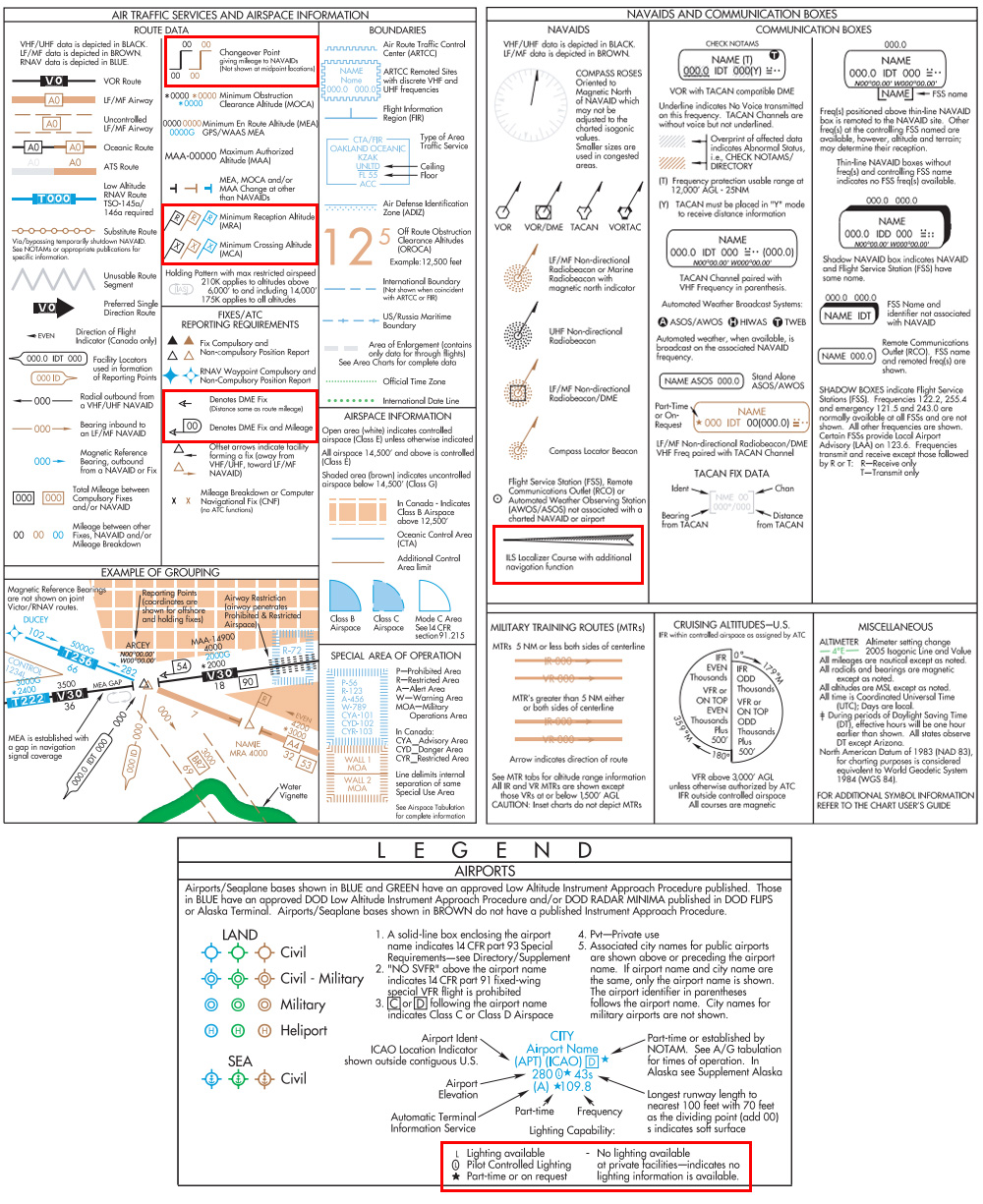
|
||||||

